
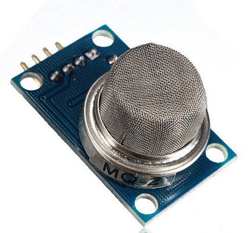
MQ-2 MQ2 Methane Butane Gas Sensor Detection Module

| รหัสสินค้า | SEN-221-02 |
| หมวดหมู่ | เซนเซอร์แก๊ส MQ-2 -> MQ-135 |
| ราคา | 60.00 บาท |
| น้ำหนัก | 10 กรัม |
| สถานะสินค้า | พร้อมส่ง |
| ลงสินค้า | 24 มี.ค. 2559 |
| อัพเดทล่าสุด | 2 ม.ค. 2568 |
| จำนวน | ชิ้น |
หยิบลงตะกร้า

รายละเอียดสินค้า
Product Description:
Introduction:
MQ-2 gas sensor sensitive material used in the clean air low conductivity tin oxide (SnO2). When there is the environment in which the combustible gas sensor, conductivity sensor with increasing concentration of combustible gases in air increases. Using a simple circuit to convert the change in conductivity of the gas concentration corresponding to the output signal. MQ-2 gas sensor high on gas, propane, hydrogen sensitivity of detection of natural gas and other flammable vapors are also very good. This sensor can detect a variety of flammable gas, is a low-cost sensors for a variety of applications.
Module Features:
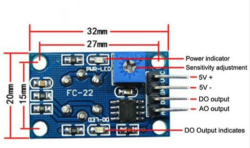
- Using high-quality dual-panel design, with power indicator and TTL signal output instructions ;
- The switching signal having a DO (TTL) output and analog output AO ;
- TTL output valid signal is low . ( Low-level signal when the output light can be directly connected to the microcontroller or relay module )
- Analog output voltage with the higher concentration of higher voltage.
- A gas, natural gas, city gas , smoke better sensitivity.
- There are four screw holes for easy positioning ;
- Product dimensions : 32 (L) * 20 (W) * 15 (H)
- Has a long life and reliable stability
- Rapid response and recovery characteristics
- Chip: LM393, ZYMQ-2 gas sensors
- Working voltage: for DC 5V
- Detection of gas: combustible gases, fumes
- Detectable concentration :300-10000ppm (flammable gas)
Electrical properties:
- Input voltage : DC5V Power consumption ( current ): 150mA
- DO output : TTL digital 0 and 1 ( 0.1 and 5V)
- AO output :0.1-0 .3 V ( relative to pollution ) , the maximum concentration of a voltage of about 4V
- Special note: After the sensor is powered , needs to warm up around 20S, measured data was stable , heat sensor is a normal phenomenon , because the internal heating wire , if hot is not normal .
Pin definition :
1, VCC: positive power supply (5V)
2, GND: power supply is negative
3, DO: TTL switching signal output
4, AO: analog signal output
Applications:
Gas may be used in homes and factories leakage monitoring device suitable for the detection of gas, butane , propane , methane , smoke , etc.
*
*
Theory
The protection resistor (4.7Kohms) and the adjustable (0-50Kohms) are in serial which forms a load resistor RL(4.7-54.7Kohms). The sensor’s resistance RS and RL forms a voltage divider. The output voltage on the signal pin could be read by Arduino or MCU via ADC. Given a value of RL , Power Supply Voltage, and output voltage, RS could be derived. Based on the chart provided in the MQ-2 datasheet, RS in clean air under given temperature and humidity is a constant,which is the “initial” resistance of the sensor named RO. RO of the resistor could be derived from RS. The main job of the calibration is to calculate the RO by sampling and averaging the readings when the module is placed in the clean air. Once the RO is derived, the concentration of target gas could be calculated by using the RS/RO ratio as the input. To achieve more accuracy, a segmented look-up table should be used. However, in the demonstration, a linear formula is used as an approximation to the original curve.
Arduino Sample Code
|
1
2
3
4
5
6
7
8
9
10
11
12
13
14
15
16
17
18
19
20
21
22
23
24
25
26
27
28
29
30
31
32
33
34
35
36
37
38
39
40
41
42
43
44
45
46
47
48
49
50
51
52
53
54
55
56
57
58
59
60
61
62
63
64
65
66
67
68
69
70
71
72
73
74
75
76
77
78
79
80
81
82
83
84
85
86
87
88
89
90
91
92
93
94
95
96
97
98
99
100
101
102
103
104
105
106
107
108
109
110
111
112
113
114
115
116
117
118
119
120
121
122
123
124
125
126
127
128
129
130
131
132
133
134
135
136
137
138
139
140
141
142
143
144
145
146
147
148
149
150
151
152
153
154
155
156
157
158
159
160
161
162
163
164
165
166
167
|
/*******************Demo for MQ-2 Gas Sensor Module V1.0*****************************
Support: Tiequan Shao: support[at]sandboxelectronics.com
Lisence: Attribution-NonCommercial-ShareAlike 3.0 Unported (CC BY-NC-SA 3.0)
Note: This piece of source code is supposed to be used as a demostration ONLY. More
sophisticated calibration is required for industrial field application.
Sandbox Electronics 2011-04-25
************************************************************************************/
/************************Hardware Related Macros************************************/
#define MQ_PIN (0) //define which analog input channel you are going to use
#define RL_VALUE (5) //define the load resistance on the board, in kilo ohms
#define RO_CLEAN_AIR_FACTOR (9.83) //RO_CLEAR_AIR_FACTOR=(Sensor resistance in clean air)/RO,
//which is derived from the chart in datasheet
/***********************Software Related Macros************************************/
#define CALIBARAION_SAMPLE_TIMES (50) //define how many samples you are going to take in the calibration phase
#define CALIBRATION_SAMPLE_INTERVAL (500) //define the time interal(in milisecond) between each samples in the
//cablibration phase
#define READ_SAMPLE_INTERVAL (50) //define how many samples you are going to take in normal operation
#define READ_SAMPLE_TIMES (5) //define the time interal(in milisecond) between each samples in
//normal operation
/**********************Application Related Macros**********************************/
#define GAS_LPG (0)
#define GAS_CO (1)
#define GAS_SMOKE (2)
/*****************************Globals***********************************************/
float LPGCurve[3] = {2.3,0.21,-0.47}; //two points are taken from the curve.
//with these two points, a line is formed which is "approximately equivalent"
//to the original curve.
//data format:{ x, y, slope}; point1: (lg200, 0.21), point2: (lg10000, -0.59)
float COCurve[3] = {2.3,0.72,-0.34}; //two points are taken from the curve.
//with these two points, a line is formed which is "approximately equivalent"
//to the original curve.
//data format:{ x, y, slope}; point1: (lg200, 0.72), point2: (lg10000, 0.15)
float SmokeCurve[3] ={2.3,0.53,-0.44}; //two points are taken from the curve.
//with these two points, a line is formed which is "approximately equivalent"
//to the original curve.
//data format:{ x, y, slope}; point1: (lg200, 0.53), point2: (lg10000, -0.22)
float Ro = 10; //Ro is initialized to 10 kilo ohms
void setup()
{
Serial.begin(9600); //UART setup, baudrate = 9600bps
Serial.print("Calibrating...\n");
Ro = MQCalibration(MQ_PIN); //Calibrating the sensor. Please make sure the sensor is in clean air
//when you perform the calibration
Serial.print("Calibration is done...\n");
Serial.print("Ro=");
Serial.print(Ro);
Serial.print("kohm");
Serial.print("\n");
}
void loop()
{
Serial.print("LPG:");
Serial.print(MQGetGasPercentage(MQRead(MQ_PIN)/Ro,GAS_LPG) );
Serial.print( "ppm" );
Serial.print(" ");
Serial.print("CO:");
Serial.print(MQGetGasPercentage(MQRead(MQ_PIN)/Ro,GAS_CO) );
Serial.print( "ppm" );
Serial.print(" ");
Serial.print("SMOKE:");
Serial.print(MQGetGasPercentage(MQRead(MQ_PIN)/Ro,GAS_SMOKE) );
Serial.print( "ppm" );
Serial.print("\n");
delay(200);
}
/****************** MQResistanceCalculation ****************************************
Input: raw_adc - raw value read from adc, which represents the voltage
Output: the calculated sensor resistance
Remarks: The sensor and the load resistor forms a voltage divider. Given the voltage
across the load resistor and its resistance, the resistance of the sensor
could be derived.
************************************************************************************/
float MQResistanceCalculation(int raw_adc)
{
return ( ((float)RL_VALUE*(1023-raw_adc)/raw_adc));
}
/***************************** MQCalibration ****************************************
Input: mq_pin - analog channel
Output: Ro of the sensor
Remarks: This function assumes that the sensor is in clean air. It use
MQResistanceCalculation to calculates the sensor resistance in clean air
and then divides it with RO_CLEAN_AIR_FACTOR. RO_CLEAN_AIR_FACTOR is about
10, which differs slightly between different sensors.
************************************************************************************/
float MQCalibration(int mq_pin)
{
int i;
float val=0;
for (i=0;i<CALIBARAION_SAMPLE_TIMES;i++) { //take multiple samples
val += MQResistanceCalculation(analogRead(mq_pin));
delay(CALIBRATION_SAMPLE_INTERVAL);
}
val = val/CALIBARAION_SAMPLE_TIMES; //calculate the average value
val = val/RO_CLEAN_AIR_FACTOR; //divided by RO_CLEAN_AIR_FACTOR yields the Ro
//according to the chart in the datasheet
return val;
}
/***************************** MQRead *********************************************
Input: mq_pin - analog channel
Output: Rs of the sensor
Remarks: This function use MQResistanceCalculation to caculate the sensor resistenc (Rs).
The Rs changes as the sensor is in the different consentration of the target
gas. The sample times and the time interval between samples could be configured
by changing the definition of the macros.
************************************************************************************/
float MQRead(int mq_pin)
{
int i;
float rs=0;
for (i=0;i<READ_SAMPLE_TIMES;i++) {
rs += MQResistanceCalculation(analogRead(mq_pin));
delay(READ_SAMPLE_INTERVAL);
}
rs = rs/READ_SAMPLE_TIMES;
return rs;
}
/***************************** MQGetGasPercentage **********************************
Input: rs_ro_ratio - Rs divided by Ro
gas_id - target gas type
Output: ppm of the target gas
Remarks: This function passes different curves to the MQGetPercentage function which
calculates the ppm (parts per million) of the target gas.
************************************************************************************/
int MQGetGasPercentage(float rs_ro_ratio, int gas_id)
{
if ( gas_id == GAS_LPG ) {
return MQGetPercentage(rs_ro_ratio,LPGCurve);
} else if ( gas_id == GAS_CO ) {
return MQGetPercentage(rs_ro_ratio,COCurve);
} else if ( gas_id == GAS_SMOKE ) {
return MQGetPercentage(rs_ro_ratio,SmokeCurve);
}
return 0;
}
/***************************** MQGetPercentage **********************************
Input: rs_ro_ratio - Rs divided by Ro
pcurve - pointer to the curve of the target gas
Output: ppm of the target gas
Remarks: By using the slope and a point of the line. The x(logarithmic value of ppm)
of the line could be derived if y(rs_ro_ratio) is provided. As it is a
logarithmic coordinate, power of 10 is used to convert the result to non-logarithmic
value.
************************************************************************************/
int MQGetPercentage(float rs_ro_ratio, float *pcurve)
{
return (pow(10,( ((log(rs_ro_ratio)-pcurve[1])/pcurve[2]) + pcurve[0])))
|
เงื่อนไขอื่นๆ
MQ-2 - Methane, Butane, LPG, smoke MQ-3 - Alcohol, Ethanol, smoke MQ-4 - Methane, CNG Gas MQ-5 - Natural gas, LPG MQ-6 - LPG, butane gas MQ-7 - Carbon Monoxide MQ-8 - Hydrogen Gas MQ-9 - Carbon Monoxide, flammable gasses MQ131 - Ozone MQ135 - Air Quality (CO, Ammonia, Benzene, Alcohol, smoke) MQ136 - Hydrogen Sulfide gas MQ137 - Ammonia MQ138 - Benzene, Toluene, Alcohol, Acetone, Propane, Formaldehyde gas, Hydrogen MQ214 - Methane, Natural gas MQ216 - Natural gas, Coal gas
วิธีการชำระเงิน
ชำระเงินผ่านธนาคาร
ชำระเงินด้วยการ Scan QR


กิตติ แซ่เอี้ยว
096-xxxxxx-3
Accept All Banks | รับเงินได้จากทุกธนาคาร
ชำระเงินออนไลน์
- ค่าธรรมเนียม 3.9% + 11 THB
- การชำระผ่าน PayPal คุณไม่จำเป็นต้องแจ้งชำระเงิน เนื่องจากระบบจะจัดการให้คุณทันที ที่คุณชำระเงินเสร็จสมบูรณ์
MEMBER
Join เป็นสมาชิกร้านค้า
ร้านmcucity
/www.mcucity.com/
สมัครสมาชิกร้านนี้ เพื่อรับสิทธิพิเศษ


- พิมพ์ “mcucity” ในช่อง Search
- หรือเข้าจากรายการร้านค้าโปรดของฉัน
สินค้าในตะกร้า ({{total_num}} รายการ)

ขออภัย ขณะนี้ยังไม่มีสินค้าในตะกร้า
ราคาสินค้าทั้งหมด
฿ {{price_format(total_price)}}
- ฿ {{price_format(discount.price)}}
ราคาสินค้าทั้งหมด
{{total_quantity}} ชิ้น
฿ {{price_format(after_product_price)}}
ราคาไม่รวมค่าจัดส่ง
➜ เลือกซื้อสินค้าเพิ่ม