
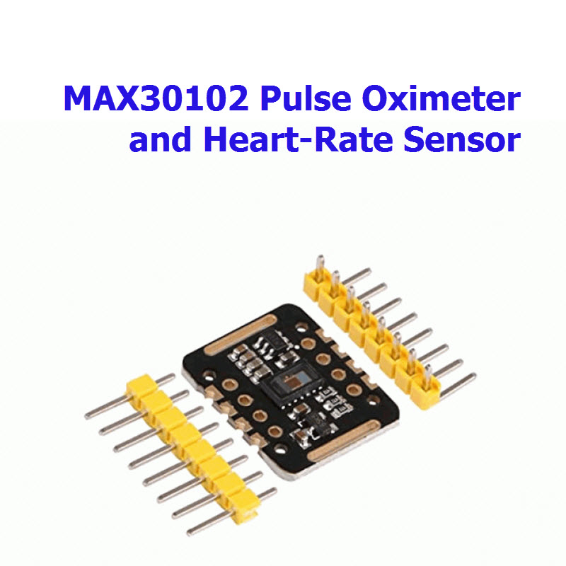
MAX30102 Pulse Oximeter and Heart-Rate Sensor

| รหัสสินค้า | M3757 |
| หมวดหมู่ | ร่างกาย ECG EKG EMG |
| ราคา | 75.00 บาท |
| น้ำหนัก | 5 กรัม |
| สถานะสินค้า | พร้อมส่ง |
| ลงสินค้า | 27 ก.ค. 2564 |
| อัพเดทล่าสุด | 21 ก.ย. 2564 |
| จำนวน | Unit |

รายละเอียดสินค้า
*

*
เงื่อนไขอื่นๆ
Pulse Sensor Amped
Arduino Code v1.2 Walkthrough
Before we get into the line-by-line stuff, there's some things to know about the signal we are going to process, and the known techniques of doing it. No sense in reinventing the algorithm!
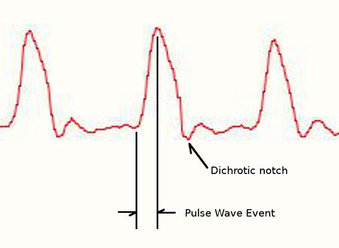
The Pulse Sensor that we make is essentially a photoplethysmograph, which is a well known medical device used for non-invasive heart rate monitoring. Sometimes, photoplethysmographs measure blood-oxygen levels (SpO2), sometimes they don't. The heart pulse signal that comes out of a photoplethysmograph is an analog fluctuation in voltage, and it has a predictable wave shape as shown in figure 1. The depiction of the pulse wave is called a photoplethysmogram, or PPG. Our latest hardware version, Pulse Sensor Amped, amplifies the raw signal of the previous Pulse Sensor, and normalizes the pulse wave around V/2 (midpoint in voltage). Pulse Sensor Amped responds to relative changes in light intensity. If the amount of light incident on the sensor remains constant, the signal value will remain at (or close to) 512 (midpoint of ADC range). More light and the signal goes up. Less light, the opposite. Light from the green LED that is reflected back to the sensor changes during each pulse.
Our goal is to find successive moments of instantaneous heart beat and measure the time between, called the Inter Beat Interval (IBI). By following the predictable shape and pattern of the PPG wave, we are able to do just that.
Now, we're not heart researchers, but we play them on this blog. We're basing this page on Other People's Research that seem reasonable to us (references below). When the heart pumps blood through the body, with every beat there is a pulse wave (kind of like a shock wave) that travels along all arteries to the very extremities of capillary tissue where the Pulse Sensor is attached. Actual blood circulates in the body much slower than the pulse wave travels. Let's follow events as they progress from point 'T' on the PPG below. A rapid upward rise in signal value occurs as the pulse wave passes under the sensor, then the signal falls back down toward the normal point. Sometimes, the dicroic notch (downward spike) is more pronounced than others, but generally the signal settles down to background noise before the next pulse wave washes through. Since the wave is repeating and predictable, we could choose almost any recognizable feature as a reference point, say the peak, and measure the heart rate by doing math on the time between each peak. This, however, can run into false readings from the dicroic notch, if present, and may be susceptible to inaccuracy from baseline noise as well.There are other good reasons not to base the beat-finding algorithm on arbitrary wave phenomena. Ideally, we want to find the instantaneous moment of the heart beat. This is important for accurate BPM calculation, Heart Rate Variability (HRV) studies, and Pulse Transit Time (PTT) measurement. And it is a worthy challenge! People Smarter Than Us (note1) argue that the instantaneous moment of heart beat happens at some point during that fast upward rise in the PPG waveform.

Some heart researchers say it's when the signal gets to 25% of the amplitude, some say when it's 50% of the amplitude, and some say it's the point when the slope is steepest during the upward rise event. This version 1.1 of Pulse Sensor code is designed to measure the IBI by timing between moments when the signal crosses 50% of the wave amplitude during that fast upward rise. The BPM is derived every beat from an average of the previous 10 IBI times. Here's how we do it!
First off, it's important to have a regular sample rate with high enough resolution to get reliable measurement of the timing between each beat. To do this, we set up Timer2, an 8 bit hardware timer on the ATmega328 (UNO), so that it throws an interrupt every other millisecond. That gives us a sample rate of 500Hz, and beat-to-beat timing resolution of 2mS (note2). This will disable PWM output on pin 3 and 11. Also, it will disable the tone() command. This code works with Arduino UNO or Arduino PRO or Arduino Pro Mini 5V or any Arduino running with an ATmega328 and 16MHz clock.
void interruptSetup(){TCCR2A = 0x02;TCCR2B = 0x06;OCR2A = 0x7C;TIMSK2 = 0x02;sei();}
The register settings above tell Timer2 to go into CTC mode, and to count up to 124 (0x7C) over and over and over again. A prescaler of 256 is used to get the timing right so that it takes 2 milliseconds to count to 124. An interrupt flag is set every time Timer2 reaches 124, and a special function called an Interrupt Service Routine (ISR) that we wrote is run at the very next possible moment, no matter what the rest of the program is doing. sei() ensures that global interrupts are enabled. Timing is important! If you are using a different Arduino or Arduino compatible device, you will need to change this function.
If you are using a FIO or LillyPad Arduino or Arduino Pro Mini 3V or Arduino SimpleSnap or other Arduino that has ATmega168 or ATmega328 with 8MHz oscillator, change the line TCCR2B = 0x06 to TCCR2B = 0x05.
If you are using Arduino Leonardo or Adafruit's Flora or Arduino Micro or other Arduino that has ATmega32u4 running at 16MHz
void interruptSetup(){
TCCR1A = 0x00;
TCCR1B = 0x0C;
OCR1A = 0x7C;
TIMSK1 = 0x02;
sei();
}
The only other thing you will need is the correct ISR vector in the next step. ATmega32u4 devices use ISR(TIMER1_COMPA_vect)
So, when the Arduino is powered up and running with Pulse Sensor Amped plugged into analog pin 0, it constantly (every 2 mS) reads the sensor value and looks for the heart beat. Here's how that works:
ISR(TIMER2_COMPA_vect){
Signal = analogRead(pulsePin);
sampleCounter += 2;
int N = sampleCounter - lastBeatTime;
This function is called every 2 milliseconds. First thing to do is to take an analog reading of the Pulse Sensor. Next, we increment the variable sampleCounter. The sampleCounter variable is what we use to keep track of time. The variable N will help avoid noise later.
Next, we keep track of the highest and lowest values of the PPG wave, to get an accurate measure of amplitude.
if(Signal < thresh && N > (IBI/5)*3){if (Signal < T){T = Signal;}}if(Signal > thresh && Signal > P){P = Signal;}
Variable P and T hold peak and trough values, respectively. The thresh variable is initialized at 512 (middle of analog range) and changes during run time to track a point at 50% of amplitude as we will see later. There is a time period of 3/5 IBI that must pass before T gets updated as a way to avoid noise and false readings from the dicroic notch.
Now, lets check and see if we have a pulse.
if (N > 250){
if ( (Signal > thresh) && (Pulse == false) && (N > ((IBI/5)*3) ){
Pulse = true;
digitalWrite(pulsePin,HIGH);
IBI = sampleCounter - lastBeatTime;
lastBeatTime = sampleCounter;
Before we even consider looking for a heart beat, a minimum amount of time has to pass. This helps avoid high frequency noise. 250 millisecond minimum N places an upper limit of 240 BPM. If you expect to have a higher BPM, adjust this accordingly and see a doctor. When the waveform rises past the thresh value, and 3/5 of the last IBI has passed, we have a pulse! Time to set the Pulse flag and turn on the pulsePin LED. (note: if you want to do something else with pin 13, comment out this line, and the later one too). Then we calculate the time since the last beat to get IBI, and update the lastBeatTime.
The next bit is used to make sure we begin with a realistic BPM value on startup.
if(firstBeat){
if(secondBeat){
secondBeat = false;
for(int i=0; i<=9; i++){
rate[i] = IBI;
}
}
firstBeat = false;
return;
}
The boolean firstBeat is initialized as true and secondBeat is initialized as false on start up, so the very first time we find a beat and get this far in the ISR, we get kicked out by the return; in the firstBeat conditional. That will end up throwing the first IBI reading away, cause it's lousy. The second time through, we can trust (more or less) the IBI, and use it to seed the rate[] array in order to start with a more accurate BPM. The BPM is derived from an average of the last 10 IBI values, hence the need to seed.
Lets calculate BPM!
word runningTotal = 0;
for(int i=0; i<=8; i++){
rate[i] = rate[i+1];
runningTotal += rate[i];
}
rate[9] = IBI;
runningTotal += rate[9];
runningTotal /= 10;
BPM = 60000/runningTotal;
QS = true;
}
}
First, we grab a large variable, runningTotal, to collect the IBIs, then the contents of rate[] are shifted over and added to runnungTotal. The oldest IBI (11 beats ago) falls out of position 0, and the fresh IBI gets put into position 9. Then it's a simple process to average the array and calculate BPM. Last thing to do is to set the QS flag (short for Quantified Self, awesome kickstarter supporters!) so the rest of the program knows we have found the beat. That's it for the things to do when we find the beat.
There's a couple of other loose ends that need tying off before we're done, like finding the not-beat.
if (Signal < thresh && Pulse == true){
digitalWrite(13,LOW);
Pulse = false;
amp = P - T;
thresh = amp/2 + T;
P = thresh;
T = thresh;
}
Pulse was declared true during the upward rise in Pulse Sensor signal when we found the beat, above, so when the signal crosses thresh going down, we can figure that the pulse is over. A little housekeeping in clearing pulsePin and the Pulse boolean. Then the amplitude of the wave that just passed is measured, and thresh is updated with the new 50% mark. P and T are reset to the new thresh. The algorithm is now primed and ready to find the next beat.
There's one more question to ask before the ISR is done. What if there are no beats?
if (N > 2500){
thresh = 512;
P = 512;
T = 512;
firstBeat = true;
secondBeat = false;
lastBeatTime = sampleCounter;
}
Variable Name |
Refresh rate |
What It Is |
| Signal | 2mS | raw Pulse Sensor signal |
| IBI | every beat | time between heartbeats in mS |
| BPM | every beat | beats per minute |
| QS | set true every beat | must be cleared by user |
| Pulse | set true every beat | cleared by ISR |
int pulsePin = 0;int blinkPin = 13;int fadePin = 5;int fadeRate = 0;
volatile int BPM;
volatile int Signal;
volatile int IBI = 600;
volatile boolean Pulse = false;
volatile boolean QS = false;
volatile int rate[10];
volatile unsigned long sampleCounter = 0;volatile unsigned long lastBeatTime = 0;volatile int P =512;volatile int T = 512;volatile int thresh = 512;volatile int amp = 100;volatile boolean firstBeat = true;volatile boolean secondBeat = false;
void setup(){
pinMode(13,OUTPUT);
pinMode(10,OUTPUT);
Serial.begin(115200);
interruptSetup();
// analogReference(EXTERNAL);
}
Here we go. pulsePin is the analog pin number that Pulse Sensor purple wire is plugged into. You can change it if you need to. blinkPin will blink with the pulse. The fadeRate variable is used to provide an optional fading LED effect with every beat on fadePin (must be a PWM pin, but not 3 or 11). It looks nicer than the blink on pin 13. The other variables should look familiar to you now. They are declared volatile because they get used in the ISR and the other parts of the code. In the setup, pin directions are declared and the interruptSetup routine is run. The last line in setup is used only when you have a different voltage powering the Pulse Sensor than you are using to power the Arduino. Mostly, it should be commented out.
Here's the loop function. Note the delay at the end. This loop will run every 20mS. Since Signal is updated automatically, we can easily send the latest value to the Processing sketch, and you can do whatever you want with it as well, modulate a tone output on a speaker, etc. Go nuts! The 'S' that we send, and the other character prefixes, are sent so Processing knows what to do with the incoming value. Remember that the QS flag gets set when our ISR finds the heart beat, so by checking it we can know when the beat happens. inside the if statement we send the IBI and BPM values to Processing, then set the fadeVal to maximum brightness and reset the QS flag for next time. the last thing to do before the delay is to fade the LED and then we're done with the loop. Let's go over the two functions that are called in the loop.
void sendDataToProcessing(char symbol, int data ){
Serial.print(symbol);
Serial.println(data);
}
The sendDataToProcessing function does just that. it expects to get a character and an integer variable, then it sends them both serially to Processing. The value symbol tells processing what kind of data is coming, and println sends a line feed at the end, so processing knows when the serial string ends. (link to processing sketch walkthrough coming soon)
void ledFadeToBeat(){
fadeRate-= 15;
fadeRate= constrain(fadeRate,0,255);
analogWrite(fadePin, fadeRate);
}
The ledFadeToBeat function is pretty simple too. It reduces the fadeRate variable by 15 (you can change this as needed), makes sure the fadeRate doesn't roll over into negative numbers,or get higher than 255, then uses analogWrite to set the brightness if the LED on fadePin.
There you have it! Pulse Sensor Amped 1.1 in alittle more than a nutshell.
note1: Seems the folks who argue most about where the instantaneous moment of heart beat is are trying to measure Pulse Transit Time. PTT measures how long it takes for the pulse to travel from the point R on an Electro Cardiogram (ECG) to an extremity (fingertip/toe). PPG is often used in PTT studies to time pulse arrival at the extremity. Somnologists sometimes use PTT. Check the references for dorking out on acronyms!
note2: Check out section 17. '8-bit Timer/Counter2 with PWM and Asynchronous Operation' in the ATmega328 datasheet: http://www.atmel.com/Images/doc8161.pdf. The sample rate we use is mentioned most in our research. Use of Timer2 has the least conflicts with libraries and shields, That's why we picked it. If you are using a FIO or Lilypad other Arduino that runs on 8MHz (instead of 16MHz), adjust the interruptSetup so that TCCR2B = 0x05.
References
http://thorax.bmj.com/content/54/5/452.full
http://www.ncbi.nlm.nih.gov/pmc/articles/PMC1763783/pdf/v054p00452.pdf
http://lcp.mit.edu/pdf/DeshmaneThesis09.pdf
http://www.somnomedics.eu/fileadmin/SOMNOmedics/Dokumente/article_Gesche_et_al_-_Continuous_BP_Measurement_by_using_the_PTT_Comparison_to_cuff_based_method.pdf
http://www.ncbi.nlm.nih.gov/pubmed/8586120
http://erj.ersjournals.com/content/8/10/1669.long
http://www.hoc.kit.edu/downloads/PTT_for_stress-measurement_final_2.pdf
http://journal.publications.chestnet.org/article.aspx?articleid=1083218
http://iopscience.iop.org/1742-6596/307/1/012060/pdf/1742-6596_307_1_012060.pdf
http://erj.ersjournals.com/content/8/10/1669.long
http://iopscience.iop.org/1742-6596/307/1/012060/pdf/1742-6596_307_1_012060.pdf
http://daily.ctia.org/files/WIRELESS2011/showsite/doc/RC_-_Noninvasive_Cuffness.pdf
http://www.wpi.edu/Pubs/ETD/Available/etd-073106-130906/unrestricted/wjohnston.pdf
วิธีการชำระเงิน
ชำระเงินผ่านธนาคาร
ชำระเงินด้วยการ Scan QR


ชำระเงินออนไลน์
- ค่าธรรมเนียม 3.9% + 11 THB
- การชำระผ่าน PayPal คุณไม่จำเป็นต้องแจ้งชำระเงิน เนื่องจากระบบจะจัดการให้คุณทันที ที่คุณชำระเงินเสร็จสมบูรณ์
MEMBER
Join เป็นสมาชิกร้านค้า


- พิมพ์ “mcucity” ในช่อง Search
- หรือเข้าจากรายการร้านค้าโปรดของฉัน
