
DC-DC 20A 300W buck constant voltage constant current adjustable car power supply LM25116
| รหัสสินค้า | M03232 |
| หมวดหมู่ | DC-DC Step Down |
| ราคา | 154.00 บาท |
| น้ำหนัก | 50 กรัม |
| สถานะสินค้า | พร้อมส่ง |
| ลงสินค้า | 17 พ.ค. 2563 |
| อัพเดทล่าสุด | 7 ก.ค. 2568 |
| จำนวน | ชิ้น |
หยิบลงตะกร้า

Tags : power supply, step-down, แหล่งจ่ายไฟ, dc to dc, LM2596, DC-TO-DC Step up, DC-TO-DC step down, คอนเวอเตอร์, regulator, positive negative, breadboard supply, LM2576, L7805, MP2307, MP1584EN
รายละเอียดสินค้า
Synchronous rectification technology introduction:
Synchronous rectification is a new technology that uses dedicated power MOSFETs with extremely low on-state resistance to replace rectifier diodes to reduce rectification losses. It can greatly improve the efficiency of the DC / DC converter and there is no dead zone voltage caused by the Schottky barrier voltage. The power MOSFET is a voltage-controlled device, and its volt-ampere characteristic is linear when it is turned on. When the power MOSFET is used as the rectifier, the gate voltage must be synchronized with the phase of the rectified voltage to complete the rectification function, so it is called synchronous rectification. Synchronous rectification technology is to greatly reduce the rectification loss of the output end of the switching power supply, thereby improving the conversion efficiency and reducing the heating of the power supply itself.
Module parameters:
Module nature: synchronous rectification non-isolated buck constant current constant voltage module CC CV charging module
Scope of application: high-power LED constant current drive, lithium battery charging (including ferroelectric), 4V, 6V, 12V, 14V, 24V battery charging, nickel-cadmium nickel-hydrogen battery (battery pack) charging, solar panels, wind turbines
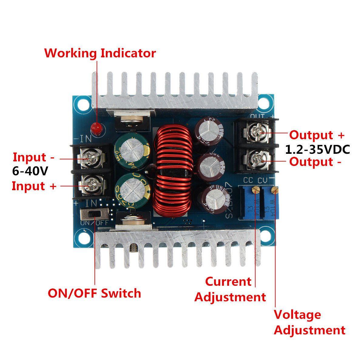
Input voltage: DC6-40V
Output voltage: continuously adjustable (1.2-35VDC) below 32V for a long time (applicable to applications where the input voltage is higher than the output voltage cannot be boosted)
Output current: Maximum 20A within 15A for a long time (please add a fan to dissipate the heat if the temperature of the power tube exceeds 65 degrees, please derate for high voltage output)
Current limit range: 0.2-20A (adjustment) module exceeds 65 degrees, please add a fan.
Minimum pressure difference: 3V
Working frequency: 150KHZ
Conversion efficiency: up to about 96% efficiency is related to pressure difference and use environment
Output ripple: Ripple is about 50mV (no noise included) 20M bandwidth (for reference only) input 24V measured
Working temperature: -10 ℃ to + 75 ℃) (Please pay attention to the temperature of the power tube in actual use, if the temperature is too high, please strengthen the heat dissipation or derating)
Potentiometer adjustment direction: clockwise (increasing), counterclockwise (decreasing)
Output short-circuit protection: Yes (instantaneous protection) constant current (currently set constant current value cannot be short-circuited for a long time )
Input reverse connection protection: none,
Output anti-backflow: No, for load self-charged or inductive load requires 2 extra tubes!
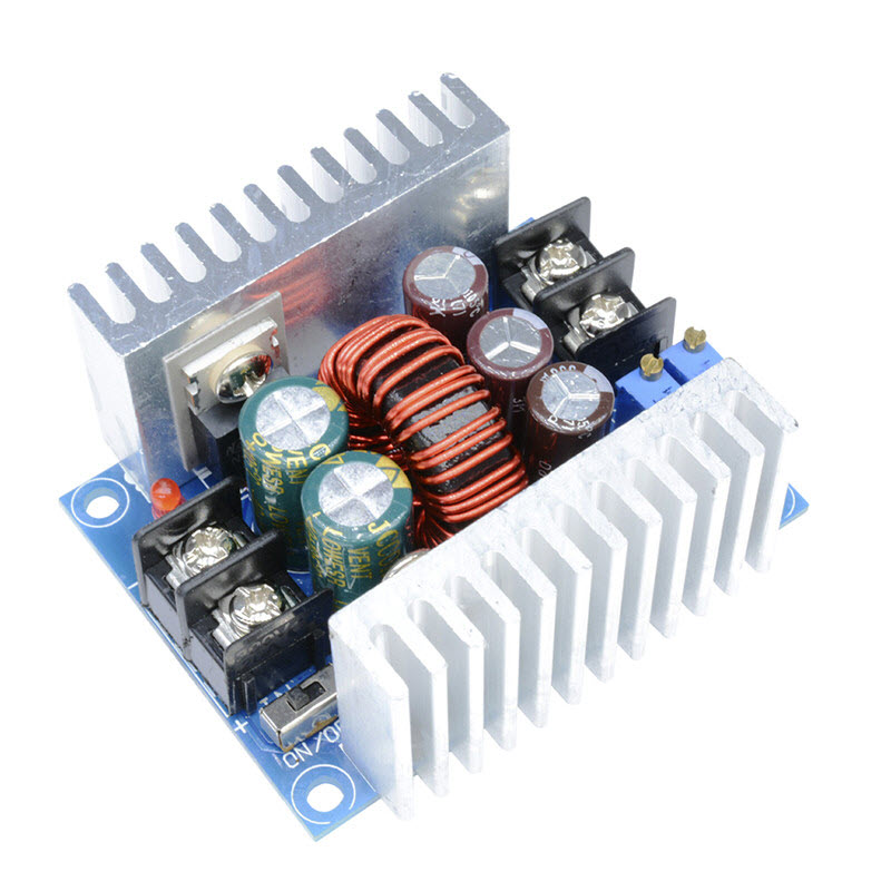
Wiring method: terminal
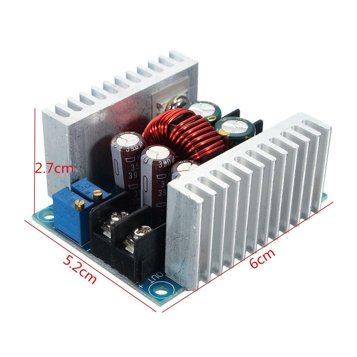
Module size: 60 * 53 * 30MM
Net weight: about 85 grams
Output current adjustment method:
1. Adjust the CV potentiometer and set the output voltage to the voltage value you need according to your load requirements.
2. Set the CC potentiometer about 30 turns counterclockwise (that is, set the output current to the minimum), connect the LED, and adjust the CC potentiometer to the current you need. For battery charging, after the battery is discharged, connect it to the output and adjust the CC to the current you need. (When charging, be sure to use the discharged battery to adjust it, because the battery has more power. More, the smaller the charging current.)
Wiring instructions:
OUT +: positive output
OUT-: negative output
+ IN: positive input-IN:
negative input
CV: output voltage adjustment
CC: output current adjustment
EN: enable, low level to turn off the output; pause, high voltage level effective
When the input and output are grounded, no-load CV output constant voltage, CC output constant current
cross-current constant voltage mode: The output voltage should be lower than 12 V
Input 12V output should be adjusted below 10V. Under constant current work. It can't be constant pressure, and it can't be constant current under constant pressure work. pick one of two
https://hackaday.io/project/185105-low-cost-solar-panel-solution-mppt-sun-tracker/log/205600-mppt-controller-hardware
https://hackaday.io/project/185105-low-cost-solar-panel-solution-mppt-sun-tracker/log/205600-mppt-controller-hardware
วิธีการชำระเงิน
ชำระเงินผ่านธนาคาร
ชำระเงินด้วยการ Scan QR


กิตติ แซ่เอี้ยว
096-xxxxxx-3
Accept All Banks | รับเงินได้จากทุกธนาคาร
ชำระเงินออนไลน์
- ค่าธรรมเนียม 3.9% + 11 THB
- การชำระผ่าน PayPal คุณไม่จำเป็นต้องแจ้งชำระเงิน เนื่องจากระบบจะจัดการให้คุณทันที ที่คุณชำระเงินเสร็จสมบูรณ์
MEMBER
Join เป็นสมาชิกร้านค้า
ร้านmcucity
/www.mcucity.com/
สมัครสมาชิกร้านนี้ เพื่อรับสิทธิพิเศษ


- พิมพ์ “mcucity” ในช่อง Search
- หรือเข้าจากรายการร้านค้าโปรดของฉัน
สินค้าในตะกร้า ({{total_num}} รายการ)

ขออภัย ขณะนี้ยังไม่มีสินค้าในตะกร้า
ราคาสินค้าทั้งหมด
฿ {{price_format(total_price)}}
- ฿ {{price_format(discount.price)}}
ราคาสินค้าทั้งหมด
{{total_quantity}} ชิ้น
฿ {{price_format(after_product_price)}}
ราคาไม่รวมค่าจัดส่ง
➜ เลือกซื้อสินค้าเพิ่ม