
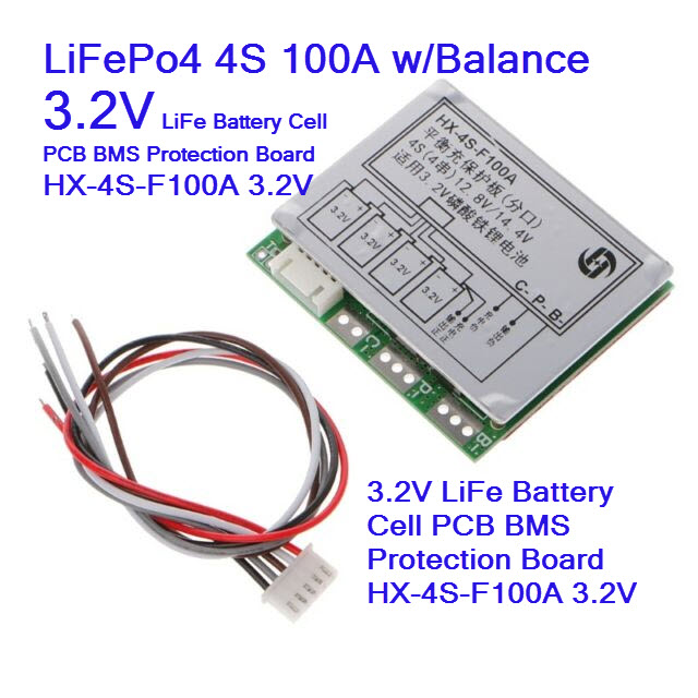
BMS 3.2V LiFePo4 4S 100A w/Balance 3.2V LiFe Battery Cell PCB BMS Protection Board
| รหัสสินค้า | M2608 |
| หมวดหมู่ | BMS LiFePo4 lithium iron phosphate 3.2V |
| ราคา | 200.00 บาท |
| น้ำหนัก | 20 กรัม |
| สถานะสินค้า | พร้อมส่ง |
| ลงสินค้า | 21 พ.ค. 2562 |
| อัพเดทล่าสุด | 20 ธ.ค. 2565 |
| จำนวน | Unit |
หยิบลงตะกร้า

Tags : lithium-ion, 18650, NCR18650B, Samsung, Panasonic, BAK, Sanyo, ICR18650, ถ่าน, แบตเตอรี่, USB, USB Power, PowerBank, Meter, Volt, Amp
รายละเอียดสินค้า
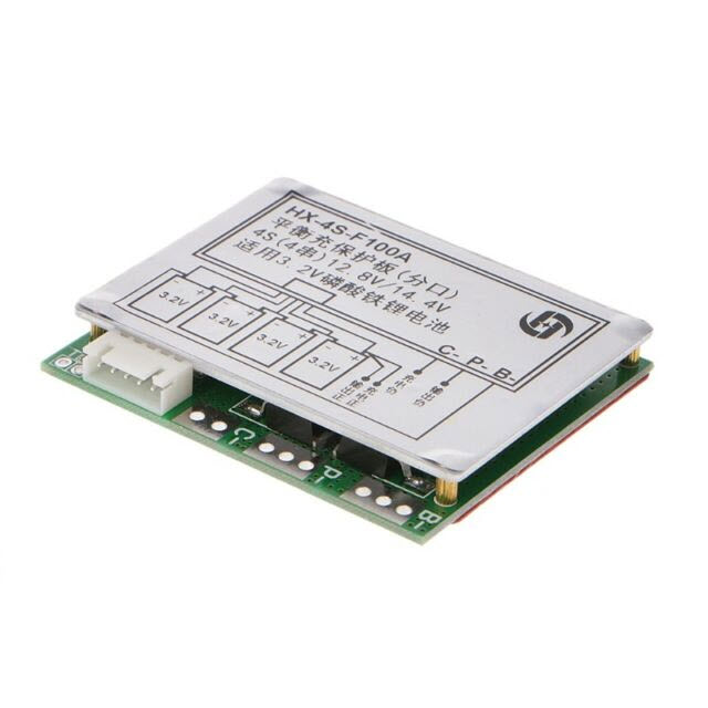
HX-4S-F100A 12.8V 4S 3.2V 14.4V 100A PCB BMS Charger Protection Board w/Balance LiFePo4
32650 LiFePo4 วงจรป้องแบตเตอรี่พร้อม Balance

100% Brand New and High Quality
This product is 4 string 12.8V LiFePo4 Lithium iron phosphate battery power protection board. With a balanced, same port 45A discharge. With heat sink.
Protection board with overcharge protection, over discharge protection, over current protection, short circuit protection, temperature protection.
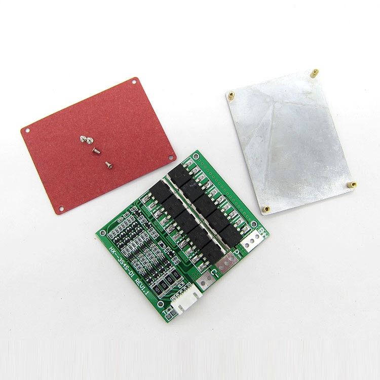
Products with 10 MOFET, powerful cooling aluminum, continuous current limit of 100A. Applicable to inverter, xenon lamp, solar street lights and other 4S battery pack.
T point Description: plus a normally closed temperature sensor switch can expand the role of temperature protection, need to remove the solder joint next to the 0R resistance.
Note: 3A current above the discharge products, the battery discharge rate to 3C or more.
Magnification calculation formula: 1C magnification of the battery, 2000 capacity is equal to 2AH * 1 = 2A upper limit current. 3C magnification battery, 2000 capacity equal to 2AH * 3 = 6A upper working current.
In the use of the battery will heat is Battery magnification is not applicable, this situation can not be long-term use, the battery will soon be damaged.

Discharge:
- Continuous Discharging Current: 100A
- Instantaneous Discharge Current: 120A
Charge:
- Charging Voltage: 14.8V (Switching power 15-16V)
- Charging Current: 10A (MAX)
Overcharge Protect:
- Over-charge Detect: 3.75±0.05V
- Protect Delay: 1300mS
- Over-charge Release: 3.60±0.05V
Balance:
- Detect Voltage: 3.60±0.05V
- Release Voltage: 3.59±0.05V
- Balance Current: 65mA
Over-discharge Protect:
- Over-discharge Detect: 2.1±0.08V
- Over-discharge Detect delay: 145S
- Release Voltage: 2.3±0.1V
Over-current Protect:
- Detect Voltage: 200mV
- Detect Delay: 20mS
- Current Detect: 120±10A
- Release Condition: Cut Load
Short-circuit Protect:
- Protect Condition: Cut Load (Not short connect)
- Detect Delay: 300uS
- Release Condition: Cut Load
- Inner Resistance: ≤20mΩ
Self-Consumption:
- Working Current: ≤30uA
- Sleep Current (when Over-discharge): ≤20uA
- Working Temperature Range: -30+80℃
PCB Board Size: 7x6cm/2.76x2.36"
Quantity: 1 Pc
Note:
Please allow 1-3mm error due to manual measurement. pls make sure you do not mind before you bid
Due to the difference between different monitors, the picture may not reflect the actual color of the item. Thank you!
No Retail Package

1 x BMS Protection Board for 12V 14.8V 4S 100A LiFePO4 Battery with Cable
*
*
เงื่อนไขอื่นๆ
The easiest DIY Lithium Polymer battery charger - A bit more
Time to add some features !
First thing you might like is a bit faster charging by providing constant current at the beginning of the charge cycle.
After that an end of charge indicator is also a nice add-on. (and automatic fan controller)
These features will add a bit more complexity, still part count is kept very low.
For better stability, I added two electrolytics capacitors on input and output.
They are not strictly needed as it is far from a challenging situation for the regulator, but it can't do harm to add them.
Value is not critical, unless you use another regulator in which case you should check the datasheet.
(Low drop regulators often need larger capacitors)
Just make sure the capacitors are rated for a voltage higher than the one in the circuit.
Instead of using a separate LM317 for constant current, it is way better to implement current limiting on the existing regulator.
By doing so, we avoid another 3V drop.

The technique is quite easy, and can be found in some LM317 datasheets, although it doesn't have much explanation.
It is pretty much the same circuit as previously, but R4 has moved on the ground line of the battery.
On previous version, R4 was used to limit current by itself.
In this one, R4 is used as a "current sense" resistor.
It doesn't limit the current alone, but voltage developped on it's pins is used to drive the regulator voltage down - effectively limiting the current output.
This is because the LM317 will regulate output voltage down to 1.25V when the ADJ pin is connected directly to ground.
So below 1.25V, we cannot tell it to decrease the voltage further to decrease the current.
(unless we have a negative voltage, but that's another story)
Adjustment is just as the first version, R1, R2, R3 have the same function - set the output voltage.
R4 is however a bit different now.
When current is passing through R4, a voltage appears between it's pins.
When that voltage reaches the threshold of +-0.7V at the base of the transistor, this one starts to conduct and it brings the ADJ pin progressively to ground.
This is just as if we had reduced the value of R2 and R3.
As current continues to increase, the transistors opens more, lowering the regulator voltage up to a point where an equilibrium is found.
The good thing is that now the value of R4 now doesn't vary with the input / output voltage ratio.
Example values for setting current with any cell count :
0.68ohm 1W = 1A0.47ohm 1W = 1.5A1.2ohm 500mW = 550mA
Note the lower power rating of the resistor. It is now the voltage regulator that does the regulation job and dissipates the heat.
This again means a heat sink and probably fan is not optional.
If you want to check the constant current value, you cannot simply short the battery leads together.
You must use a resistor in serie to make sure voltage on the + pin doesn't fall below 1.25V.
A 2,2ohm 5W resistor is ok to test currents from 0.5 to 1.5 amps.
วิธีการชำระเงิน
ชำระเงินผ่านธนาคาร
ชำระเงินด้วยการ Scan QR


กิตติ แซ่เอี้ยว
096-xxxxxx-3
Accept All Banks | รับเงินได้จากทุกธนาคาร
ชำระเงินออนไลน์
- ค่าธรรมเนียม 3.9% + 11 THB
- การชำระผ่าน PayPal คุณไม่จำเป็นต้องแจ้งชำระเงิน เนื่องจากระบบจะจัดการให้คุณทันที ที่คุณชำระเงินเสร็จสมบูรณ์
MEMBER
Join เป็นสมาชิกร้านค้า
ร้านmcucity
/www.mcucity.com/
สมัครสมาชิกร้านนี้ เพื่อรับสิทธิพิเศษ


- พิมพ์ “mcucity” ในช่อง Search
- หรือเข้าจากรายการร้านค้าโปรดของฉัน
สินค้าในตะกร้า ({{total_num}} รายการ)

ขออภัย ขณะนี้ยังไม่มีสินค้าในตะกร้า
ราคาสินค้าทั้งหมด
฿ {{price_format(total_price)}}
- ฿ {{price_format(discount.price)}}
ราคาสินค้าทั้งหมด
{{total_quantity}} ชิ้น
฿ {{price_format(after_product_price)}}
ราคาไม่รวมค่าจัดส่ง
➜ เลือกซื้อสินค้าเพิ่ม