
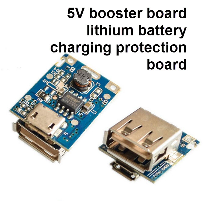
5V 134N3P Step-Up Power Module Lithium Battery Charging Protection Board
| รหัสสินค้า | M1698 |
| หมวดหมู่ | บอร์ดชาร์ท/ควบคุม แบต/BMS |
| ราคา | 10.00 บาท |
| น้ำหนัก | 10 กรัม |
| ลงสินค้า | 23 ธ.ค. 2560 |
| อัพเดทล่าสุด | 20 ก.ย. 2566 |
ขออภัย สินค้าหมด

Tags : lithium-ion, 18650, NCR18650B, Samsung, Panasonic, BAK, Sanyo, ICR18650, ถ่าน, แบตเตอรี่, USB, USB Power, PowerBank, Meter, Volt, Amp
รายละเอียดสินค้า
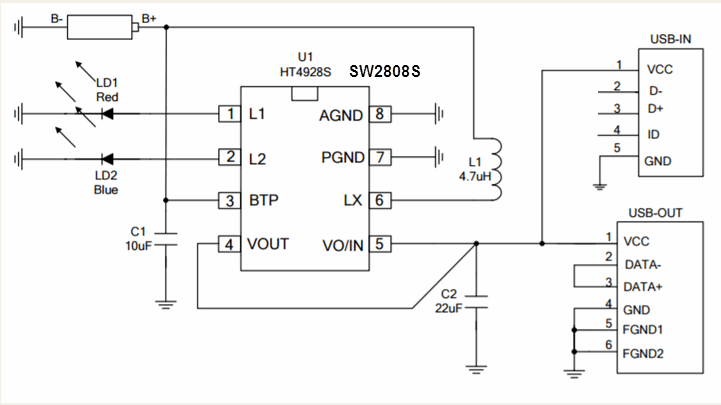
HT4928S / SW8208S
product description
HT4928S is a very high degree of integration of the mobile power management chip,
built-in charging management module, LED indication module, a booster module discharge
management, and the use of small SOP8 package, the periphery of minimal elements,
can form a powerful mobile power scheme.
Main feature
◆ highly integrated, minimal external components;
◆ built-in fixed 0.8A linear charging mode;
◆ trickle / constant-current / constant-voltage three-charging, constant voltage 4.20 V (typical), support 0V battery;
◆ built-in charge temperature can be automatically reduced in accordance with the electric charge flow, 130 degrees began to decrease, it can be reduced to a minimum 0;
◆ charge input anti-backfeed function is not required the anti-backfeed diodes;
◆ boost synchronous rectification circuit, up to 91% efficiency, low heat, a fixed 5.1V output, no external resistor;
◆ output (typical battery 3.6V) current 0.8A, having a constant power output, a complete overcurrent, short circuit protection;
◆ load inserted automatically start boost, remove the load automatic sleep;
◆ low battery alerts;
◆ single / dual lamp indication of charging and discharging;
◆ shared input / output ports, identification charge / discharge;
◆ 4KV ESD;
◆ fixed switching frequency 1MHZ;
◆ battery overcharge, over-discharge protection;
◆ SOP8 small package.
*
*
*
เงื่อนไขอื่นๆ
Description
This tiny module is perfect for charging single cell 3.7V 1 Ah or higher LiPo cells such as 16550s that don't have their own protection circuit.
Based around the TP4056 charger IC and DW01 battery protection IC this module will offer 1A charge current then cut off when finished.
Futhermore when the battery voltage drops below 2.4V the protection IC will switch the load off to protect the cell from running at too low of a voltage - and also protects against over-voltage and reverse polarity connection (it will usually destroy itself instead of the battery) however please check you have it connected correctly the first time.
Using the module
- Connect micro USB cable for power, or 5V DC to pads marked IN+ and IN- on left-hand side of the module
- Connect cell to charge to B+/B- pads on right-hand side of module
- A load (something for the battery to power) can be connected to the OUT+/OUT- pads on the right-hand side
- Important! Disconnect load when charging
- The red LED indicates chaging in progress, green LED indicates charging has finished.
- Never charge your battery at a rate greater than 1C.
Specifications
- Input voltage - 5V via microUSB or solder pads on left-hand side of module
- Full charge voltage - 4.2V
- Charging current - 1A by default. However you can change this by changing the 1k2 resistor next to the "IN-" pad the bottom-left of the board. See the Rprog table on page three of the TP4056 data sheet for different values and matching charging currents
วิธีการชำระเงิน
ชำระเงินผ่านธนาคาร
ชำระเงินด้วยการ Scan QR


กิตติ แซ่เอี้ยว
096-xxxxxx-3
Accept All Banks | รับเงินได้จากทุกธนาคาร
ชำระเงินออนไลน์
- ค่าธรรมเนียม 3.9% + 11 THB
- การชำระผ่าน PayPal คุณไม่จำเป็นต้องแจ้งชำระเงิน เนื่องจากระบบจะจัดการให้คุณทันที ที่คุณชำระเงินเสร็จสมบูรณ์
MEMBER
Join เป็นสมาชิกร้านค้า
ร้านmcucity
/www.mcucity.com/
สมัครสมาชิกร้านนี้ เพื่อรับสิทธิพิเศษ


- พิมพ์ “mcucity” ในช่อง Search
- หรือเข้าจากรายการร้านค้าโปรดของฉัน
สินค้าในตะกร้า ({{total_num}} รายการ)

ขออภัย ขณะนี้ยังไม่มีสินค้าในตะกร้า
ราคาสินค้าทั้งหมด
฿ {{price_format(total_price)}}
- ฿ {{price_format(discount.price)}}
ราคาสินค้าทั้งหมด
{{total_quantity}} ชิ้น
฿ {{price_format(after_product_price)}}
ราคาไม่รวมค่าจัดส่ง
➜ เลือกซื้อสินค้าเพิ่ม