
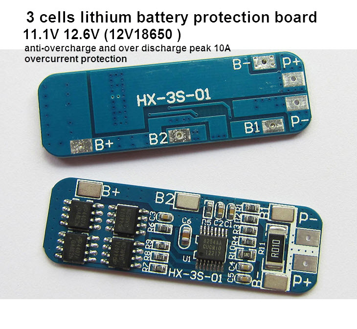
โมดูลป้องกัน แบตเตอรี่ลิเธียม ขนาด 3 เซล 11.1V 12.6V กระแสสูงสุด 10A
| รหัสสินค้า | M1079 |
| หมวดหมู่ | บอร์ดชาร์ท/ควบคุม แบต/BMS |
| ราคา | 28.00 บาท |
| น้ำหนัก | 3 กรัม |
| สถานะสินค้า | พร้อมส่ง |
| ลงสินค้า | 16 ก.พ. 2560 |
| อัพเดทล่าสุด | 23 ก.ย. 2567 |
| จำนวน | Unit |

รายละเอียดสินค้า
anti-overcharge and over discharge peak 10A overcurrent protection
3 series (three 18650 batteries or lithium polymer series combination)
10.8V (polymer battery rated voltage)
11.1V (18650 or 3.7V lithium battery rated voltage)
12.6V (Li-ion battery fully charged voltage)
Discharge 10A (refer to the upper limit of the discharge current limit)
Note 1: in strict accordance with the wiring diagram 0V (B -), 3.7V (B1), 7.4V (B2), 11.1V (B +), do not deliberately short-circuited!
Note 2: The need to take a good line charge, will have output.
Note 3: 3 series battery pack, make sure the voltage of each battery, if not the same, please separate each battery is full again in tandem. . . Discharge test, the voltage drop that fast battery cell is a difference.
For some electronic poor customer base explain: Do not put the battery and battery poor mix using three battery capacity / resistance the closer the better (2 + 1 difference between the battery cells effect!! 3 = poor battery effect).
The lithium battery protection board attributes:
Model: HX-3S-01 charging
voltage range: 4.25-4.35v ± 0.05v
Size: 50 * 16 * 1.0mm
over-discharge voltage range: 2.3-3.0v ± 0.05v
Limit working current: 5-8A Operating Temperature: -40 -- + 50 ℃
Limit instantaneous current: 9-10A storage conditions: -40-- + 80 ℃
Static current: less than 30uA active life: more than 30,000 hours
Resistance: less than 100mΩ short-circuit protection: protect, delay self-recovery.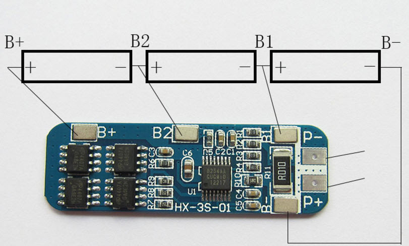
The protective plate size and device description;
The protective plate size is 50 * 16 * 1.2mm;
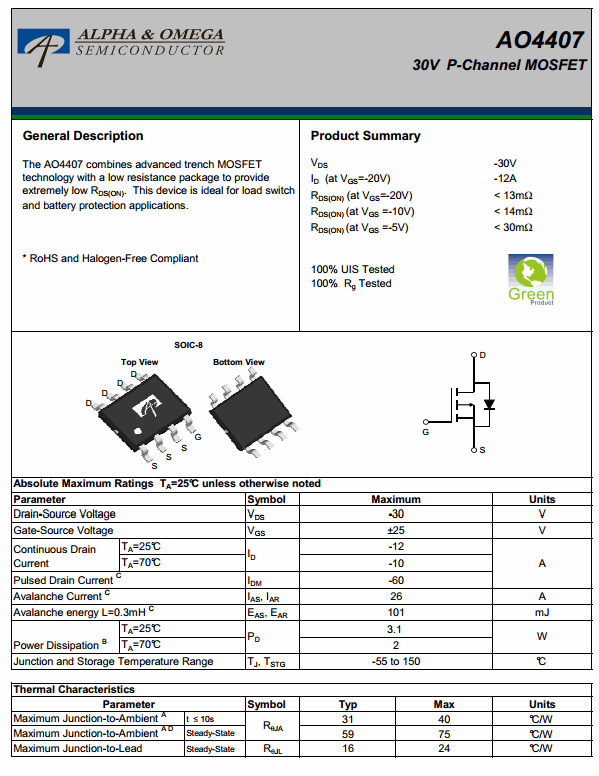
Component Seiko S-8254AA protect the chip and AO4407 * 4;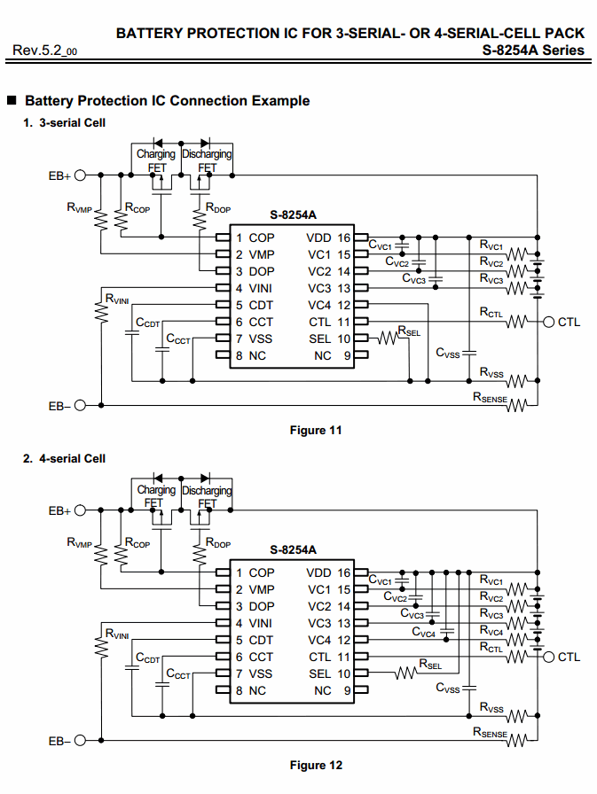
เงื่อนไขอื่นๆ
The easiest DIY Lithium Polymer battery charger - A bit more

This is because the LM317 will regulate output voltage down to 1.25V when the ADJ pin is connected directly to ground.
So below 1.25V, we cannot tell it to decrease the voltage further to decrease the current.
(unless we have a negative voltage, but that's another story)
0.68ohm 1W = 1A0.47ohm 1W = 1.5A1.2ohm 500mW = 550mA
วิธีการชำระเงิน
ชำระเงินผ่านธนาคาร
ชำระเงินด้วยการ Scan QR


ชำระเงินออนไลน์
- ค่าธรรมเนียม 3.9% + 11 THB
- การชำระผ่าน PayPal คุณไม่จำเป็นต้องแจ้งชำระเงิน เนื่องจากระบบจะจัดการให้คุณทันที ที่คุณชำระเงินเสร็จสมบูรณ์
MEMBER
Join เป็นสมาชิกร้านค้า


- พิมพ์ “mcucity” ในช่อง Search
- หรือเข้าจากรายการร้านค้าโปรดของฉัน
